


 广告
广告


FLUENT电池组放电过程模拟
2018-05-04 09:56:09· 来源:南流坊

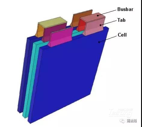
本案例演示1P3S锂离子电池组放电问题的模拟过程。
本案例演示1P3S锂离子电池组放电问题的模拟过程。案例模型如下图所示。
案例中,电池组的放电过程发生在200瓦的恒定功率下,电池容量是14.6Ah。
1、启动FLUENT并导入网格
(1)在Windows系统下执行“开始”→“所有程序”→ANSYS 18.1→Fluid Dynamics→FLUENT 18.1命令,启动FLUENT 18.1。
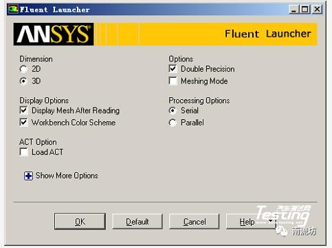
(2)在FLUENT Launcher界面中的Dimension中选择3D,在Display Options中勾选Display Mesh After Reading,Embed Graphics Windows和Workbench Color Scheme,单击OK按钮进入FLUENT主界面。
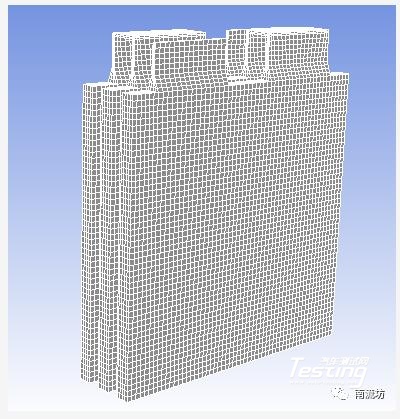
(3)在FLUENT主界面中,单击主菜单中File→Read→Mesh按钮,弹出Select File(导入网格)对话框,选择文件名为1P3S_battery_pack.msh的网格文件,单击OK按钮便可导入网格。
(4)导入网格后,在图形显示区将显示几何模型。
(5)单击主菜单中Mesh→Check按钮,检查网格质量,确保不存在负体积。
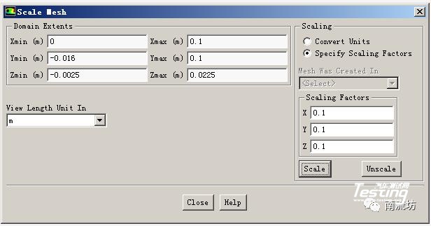
(6)单击主菜单中Mesh→Scale按钮,弹出如图5所示Scale Mesh(网格缩放)对话框。在Scaling中,选择Special Scaling Factors,在Scaling Factors X,Y和Z中分别输入0.1,单击Scale完成网格缩放。
(7)单击主菜单中File→Write→Case按钮,弹出Select File(保存项目)对话框,在Case File中填入battery,单击OK按钮便可保存项目。
2、调入MSMD电池模型
(1)在文本信息区,依次输入以下指令
> define
/define> models
/define/models> addon-module
Fluent Addon Modules:
0. None
1. MHD Model
2. Fiber Model
3. Fuel Cell and Electrolysis Model
4. SOFC Model with Unresolved Electrolyte
5. Population Balance Model
6. Adjoint Solver
7. Single-Potential Battery Model
8. Dual-Potential MSMD Battery Model
9. PEM Fuel Cell Model
10. Macroscopic Particle Model
Enter Module Number: [0] 8
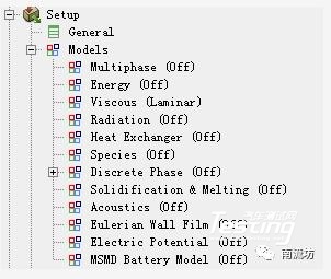
(2)输入8,选择导入MSMD电池模型。一旦MSMD电池模型被加载,MSMD电池模型将出现在模型树中。
3、定义求解器
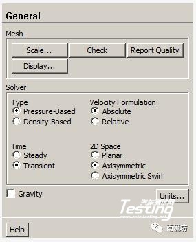
(1)单击主菜单中Define→General按钮,弹出General(总体模型设定)面板。在Solver中,Time类型选择Transient。
(2)在模型设定面板双击Energy按钮,弹出Energy(能量模型)对话框,勾选Energy Equation激活能量方程,单击OK按钮确认。
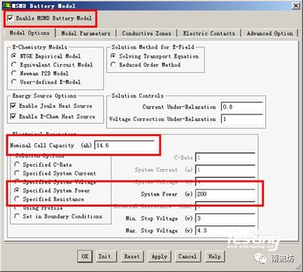
(3)在模型设定面板双击MSMD Battery Model按钮,弹出MSMD Battery Model(MSMD电池模型)对话框,勾选Enable the battery model激活MSMD电池模型。
在Nominal Cell Capacity中输入14.6,在Solution Options中选择Specified System Power,在System Power中输入200。
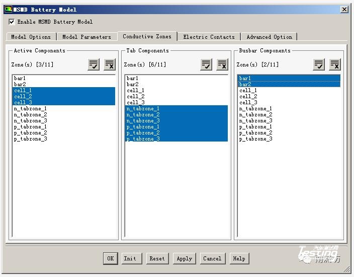
(4)在Conductive Zones选项卡中,按照下图进行选择。
(5)在Electric Contacts选项卡中,按照下图进行选择。
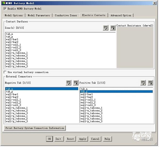
(6)在Electric Contacts选项卡中,点击Print Battery System Connection Information按钮,将在文本信息框中显示如下信息。确认后,点击OK按钮关闭MSMD电池模型对话框。
.jpg)
4、设置材料
(1)单击主菜单中Define→Materials按钮,弹出Materials(材料)面板。在材料面板中,点击Create/Edit按钮便可弹出Create/Edit Materials(物性参数设定)对话框。
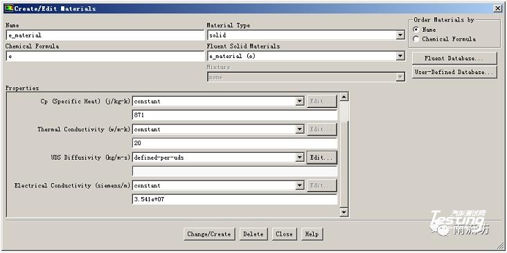
(2)在物性参数设定对话框中,按照以下参数设定新物质e_material。
a.Material Type选择solid
b.Name中输入e_material,Chemical Formula中输入e
c.Thermal Conductivity中输入20
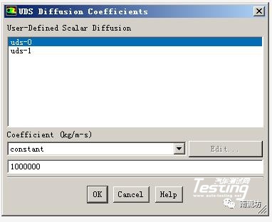
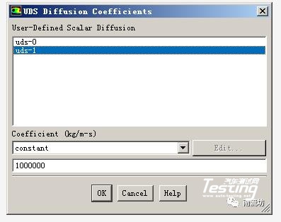
f.UDS Diffusivity选择define-per-uds,在弹出的UDS Diffusivity Coefficients对话框中,设定uds-0和uds-1的Coefficient均为1.0e6。
(3)点击Change/Create按钮完成新物质的设定。
(4)在物性参数设定对话框中,按照以下参数设定新物质busbar_material。
a.Material Type选择solid
b.Name中输入busbar_material,Chemical Formula中输入bus
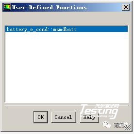
c.UDS Diffusivity选择user-defined,在弹出的User-Defined Functions对话框中,选择battery_e_cond::msmdbatt,点击OK按钮确认。
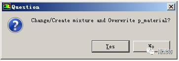
点击Change/Create按钮,在弹出的Question对话框中,单击No按钮创建新物质。
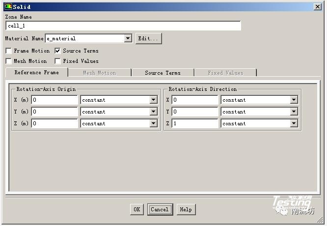
5、设置计算域
(1)单击主菜单中Define→Cell Zone Conditions按钮启动Cell Zone Condition(区域条件)面板。
对应e_zone、tab_pzone和tab_nzone在Material Name中选择相应的e_material、p_material和n_material。
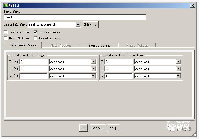
(2)设定bar_1、bar_2、n_tabzone_1、n_tabzone_2、n_tabzone_3、p_tabzone_1、p_tabzone_2和p_tabzone_3在Material Name中选择相应的busbar_material。
6、边界条件
(1)单击主菜单中Define→Boundary Conditions按钮启动的边界条件面板。
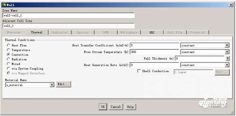
(2)在边界条件面板中,双击wall-cell_1弹出边界条件设置对话框。
在Thermal选项卡中,Thermal Conditions选择Convention,在Heat Transfer Coefficient中输入5,单击OK按钮确认退出。
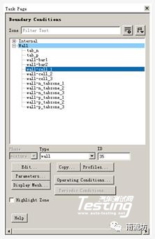
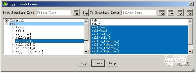
(3)在边界条件面板中,单击Copy按钮弹出Copy Conditions(边界条件复制)对话框。
在From Boundary Zone中选择wall-cell_1,在To Boundary Zone中选择wall-cell_2、wall-cell_3、wall-bar1、wall-bar2、wall-n_tabzone_1、wall-n_tabzone_2、wall-n_tabzone_3、wall-p_tabzone_1、wall-p_tabzone_2和wall-p_tabzone_3,单击Copy按钮完成复制。
7、求解控制
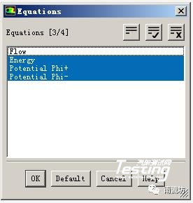
(1)单击主菜单中Solve→Methods按钮,弹出Solution Methods(求解方法设置)面板。
(2)单击Equations按钮,弹出Equations(方程)对话框,取消选择Flow,单击OK按钮确认。
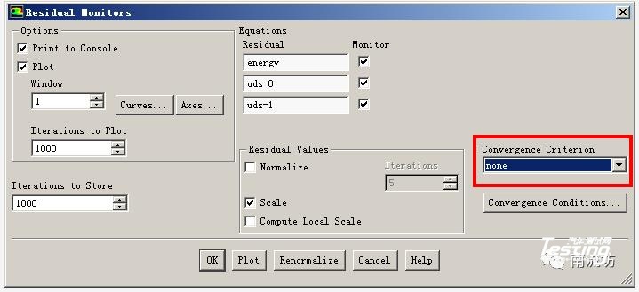
(3)单击主菜单中Solve→Monitors按钮,弹出Monitors(监视)面板,双击Residuals-Print, Plot便弹出Residual Monitors(残差监视)对话框,在Convergence Criterion中选择none。
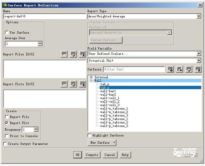
(4)在Surface Monitors下单击Create按钮弹出Surface Monitor(表面监视)对话框。
勾选Plot,在Report Type 中选择Area-Weighted Average,在Field Variable中选择User Defined Scalars和Potential Phi+,在Surface中选择tab_p,单击OK按钮确认。
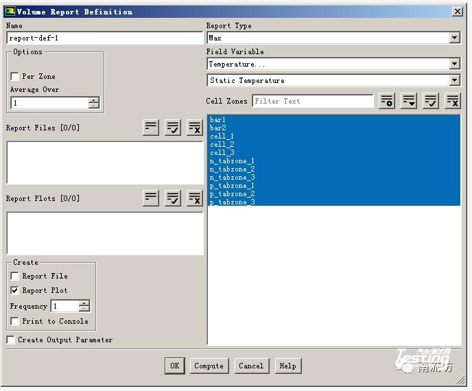
(5)在Volume Monitors下单击Create按钮弹出Volume Monitor(体积监视)对话框。
勾选Plot,在Report Type 中选择max,在Field Variable中选择Temperature和Static Temperature,在Cell Zones中选择全部,单击OK按钮确认。
8、初始条件
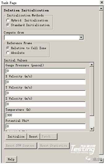
单击主菜单中Solve→Initialization按钮,弹出Solution Initialization(初始化设置)面板。
Initialization Methods中选择Standard Initialization,单击Initialize按钮进行初始化。
9、计算求解
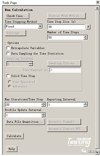
单击主菜单中Solve→Run Calculation按钮,弹出Run Calculation(运行计算)面板。
在Time Step Size中输入30,No. of Time Steps中输入50,单击Calculate开始计算。
10、结果后处理
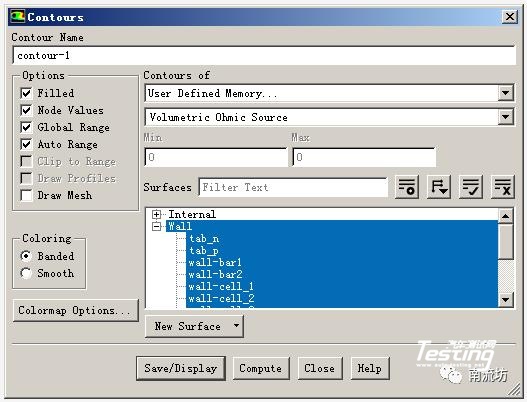
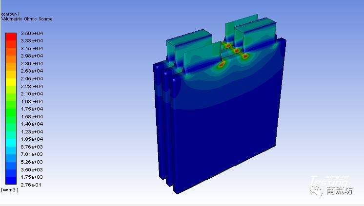
(1)在Graphics下双击Contous弹出Contous(等值线)对话框。
Contous of选择User Defined Memory和Volumetric Ohmic Source,在Surface Types中选择wall,单击Display按钮,显示云图。
案例中,电池组的放电过程发生在200瓦的恒定功率下,电池容量是14.6Ah。
1、启动FLUENT并导入网格
(1)在Windows系统下执行“开始”→“所有程序”→ANSYS 18.1→Fluid Dynamics→FLUENT 18.1命令,启动FLUENT 18.1。
(2)在FLUENT Launcher界面中的Dimension中选择3D,在Display Options中勾选Display Mesh After Reading,Embed Graphics Windows和Workbench Color Scheme,单击OK按钮进入FLUENT主界面。
(3)在FLUENT主界面中,单击主菜单中File→Read→Mesh按钮,弹出Select File(导入网格)对话框,选择文件名为1P3S_battery_pack.msh的网格文件,单击OK按钮便可导入网格。
(4)导入网格后,在图形显示区将显示几何模型。
(5)单击主菜单中Mesh→Check按钮,检查网格质量,确保不存在负体积。
(6)单击主菜单中Mesh→Scale按钮,弹出如图5所示Scale Mesh(网格缩放)对话框。在Scaling中,选择Special Scaling Factors,在Scaling Factors X,Y和Z中分别输入0.1,单击Scale完成网格缩放。
(7)单击主菜单中File→Write→Case按钮,弹出Select File(保存项目)对话框,在Case File中填入battery,单击OK按钮便可保存项目。
2、调入MSMD电池模型
(1)在文本信息区,依次输入以下指令
> define
/define> models
/define/models> addon-module
Fluent Addon Modules:
0. None
1. MHD Model
2. Fiber Model
3. Fuel Cell and Electrolysis Model
4. SOFC Model with Unresolved Electrolyte
5. Population Balance Model
6. Adjoint Solver
7. Single-Potential Battery Model
8. Dual-Potential MSMD Battery Model
9. PEM Fuel Cell Model
10. Macroscopic Particle Model
Enter Module Number: [0] 8
(2)输入8,选择导入MSMD电池模型。一旦MSMD电池模型被加载,MSMD电池模型将出现在模型树中。
3、定义求解器
(1)单击主菜单中Define→General按钮,弹出General(总体模型设定)面板。在Solver中,Time类型选择Transient。
(2)在模型设定面板双击Energy按钮,弹出Energy(能量模型)对话框,勾选Energy Equation激活能量方程,单击OK按钮确认。
(3)在模型设定面板双击MSMD Battery Model按钮,弹出MSMD Battery Model(MSMD电池模型)对话框,勾选Enable the battery model激活MSMD电池模型。
在Nominal Cell Capacity中输入14.6,在Solution Options中选择Specified System Power,在System Power中输入200。
(4)在Conductive Zones选项卡中,按照下图进行选择。
(5)在Electric Contacts选项卡中,按照下图进行选择。
(6)在Electric Contacts选项卡中,点击Print Battery System Connection Information按钮,将在文本信息框中显示如下信息。确认后,点击OK按钮关闭MSMD电池模型对话框。
4、设置材料
(1)单击主菜单中Define→Materials按钮,弹出Materials(材料)面板。在材料面板中,点击Create/Edit按钮便可弹出Create/Edit Materials(物性参数设定)对话框。
(2)在物性参数设定对话框中,按照以下参数设定新物质e_material。
a.Material Type选择solid
b.Name中输入e_material,Chemical Formula中输入e
c.Thermal Conductivity中输入20
f.UDS Diffusivity选择define-per-uds,在弹出的UDS Diffusivity Coefficients对话框中,设定uds-0和uds-1的Coefficient均为1.0e6。
(3)点击Change/Create按钮完成新物质的设定。
(4)在物性参数设定对话框中,按照以下参数设定新物质busbar_material。
a.Material Type选择solid
b.Name中输入busbar_material,Chemical Formula中输入bus
c.UDS Diffusivity选择user-defined,在弹出的User-Defined Functions对话框中,选择battery_e_cond::msmdbatt,点击OK按钮确认。
点击Change/Create按钮,在弹出的Question对话框中,单击No按钮创建新物质。
5、设置计算域
(1)单击主菜单中Define→Cell Zone Conditions按钮启动Cell Zone Condition(区域条件)面板。
对应e_zone、tab_pzone和tab_nzone在Material Name中选择相应的e_material、p_material和n_material。
(2)设定bar_1、bar_2、n_tabzone_1、n_tabzone_2、n_tabzone_3、p_tabzone_1、p_tabzone_2和p_tabzone_3在Material Name中选择相应的busbar_material。
6、边界条件
(1)单击主菜单中Define→Boundary Conditions按钮启动的边界条件面板。
(2)在边界条件面板中,双击wall-cell_1弹出边界条件设置对话框。
在Thermal选项卡中,Thermal Conditions选择Convention,在Heat Transfer Coefficient中输入5,单击OK按钮确认退出。
(3)在边界条件面板中,单击Copy按钮弹出Copy Conditions(边界条件复制)对话框。
在From Boundary Zone中选择wall-cell_1,在To Boundary Zone中选择wall-cell_2、wall-cell_3、wall-bar1、wall-bar2、wall-n_tabzone_1、wall-n_tabzone_2、wall-n_tabzone_3、wall-p_tabzone_1、wall-p_tabzone_2和wall-p_tabzone_3,单击Copy按钮完成复制。
7、求解控制
(1)单击主菜单中Solve→Methods按钮,弹出Solution Methods(求解方法设置)面板。
(2)单击Equations按钮,弹出Equations(方程)对话框,取消选择Flow,单击OK按钮确认。
(3)单击主菜单中Solve→Monitors按钮,弹出Monitors(监视)面板,双击Residuals-Print, Plot便弹出Residual Monitors(残差监视)对话框,在Convergence Criterion中选择none。
(4)在Surface Monitors下单击Create按钮弹出Surface Monitor(表面监视)对话框。
勾选Plot,在Report Type 中选择Area-Weighted Average,在Field Variable中选择User Defined Scalars和Potential Phi+,在Surface中选择tab_p,单击OK按钮确认。
(5)在Volume Monitors下单击Create按钮弹出Volume Monitor(体积监视)对话框。
勾选Plot,在Report Type 中选择max,在Field Variable中选择Temperature和Static Temperature,在Cell Zones中选择全部,单击OK按钮确认。
8、初始条件
单击主菜单中Solve→Initialization按钮,弹出Solution Initialization(初始化设置)面板。
Initialization Methods中选择Standard Initialization,单击Initialize按钮进行初始化。
9、计算求解
单击主菜单中Solve→Run Calculation按钮,弹出Run Calculation(运行计算)面板。
在Time Step Size中输入30,No. of Time Steps中输入50,单击Calculate开始计算。
10、结果后处理
(1)在Graphics下双击Contous弹出Contous(等值线)对话框。
Contous of选择User Defined Memory和Volumetric Ohmic Source,在Surface Types中选择wall,单击Display按钮,显示云图。
- 下一篇:PCB将参加2018汽车NVH控制技术国际研讨会
- 上一篇:随机振动疲劳寿命预测方法


最新资讯
-
中汽中心工程院能量流测试设备上线全新专家
2025-04-03 08:46
-
上新|AutoHawk Extreme 横空出世-新一代实
2025-04-03 08:42
-
「智能座椅」东风日产N7为何敢称“百万级大
2025-04-03 08:31
-
基于加速度计补偿的俯仰角和路面坡度角估计
2025-04-03 08:30
-
《北京市自动驾驶汽车条例》正式实施 L3级
2025-04-02 20:23
