


 广告
广告


多相流计算之油箱晃动
2018-06-07 11:59:20· 来源:CFD之道

本案例演示利用Fluent中的VOF模型仿真计算密闭油箱晃动过程中的自由液面问题。
本案例演示利用Fluent中的VOF模型仿真计算密闭油箱晃动过程中的自由液面问题。
1案例描述
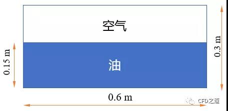
汽车在颠簸的道路上行驶时,在变加速度作用下,可能会导致油箱内液面晃动。当晃动极为剧烈时,甚至会造成油泵无法吸取燃油,因此需要利用CFD研究油箱在晃动过程中液面分布情况。为简化计算,本案例采用2D模型,3D模型的仿真思路及设置过程与此完全相同。计算域几何如图所示。
对于油箱晃动过程,在Fluent中有两种方式进行解决:
指定加速度。Fluent中可以指定流体运动加速度,并将加速度以体积力的形式施加到计算域中的流体上。然而Fluent并没有提供变加速度的直接添加,若要计算变加速度情况,则需要手工分段计算。
指定计算域速度。将加速度或位移数据转化为速度添加到计算域上。可以通过DEFINE_ZONE_MOTION宏或PROFILE文件的方式进行指定。此方式要比加速度方式更加灵活。
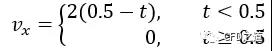
本案例假设计算区域的运动速度为:
2模型及网格
案例模型极为简单,在SCDM中创建0.6x0.3m的矩形平面,采用网格尺寸0.003m,在ICEM CFD中生成网格,共生成20000个四边形网格。

3准备UDF
利用UDF宏DEFINE_ZONE_MOTION指定区域运动。

该UDF宏可以以编译或解释的方式加载。
4Fluent设置
以2D、Double Precision方式启动Fluent,导入网格文件
4.1 General设置
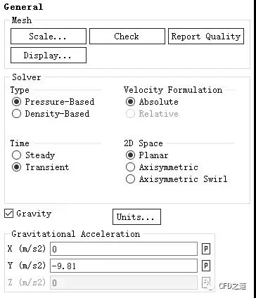
双击模型树节点General,右侧面板激活选项Transient及Gravity,设置重力加速度为Y方向-9.81 m/s2
4.2 Models设置
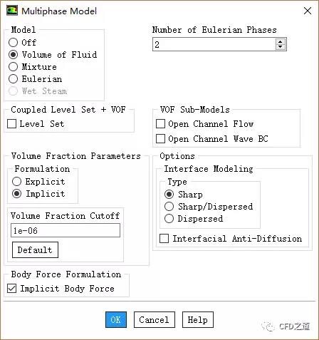
鼠标双击模型树节点Models > Multiphase,弹出的对话框中激活选项Volume of Fluid
激活选项Implicit Body Force,其他参数设置如下图所示
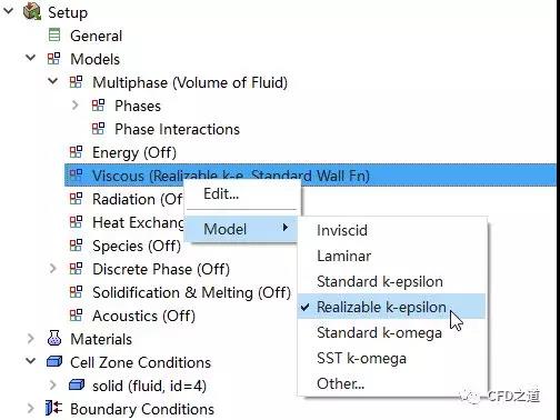
右键选择模型树节点Models > Viscous,点击弹出菜单项Model → Realizable k-epsilon激活湍流模型
4.3 Materials设置
添加材料water-liquid,采用默认材料参数。这里可以将材料参数改成汽油的参数,我就懒得改了,后面就用水代替油了。
4.4 Phase设置
右键选择模型树节点Models > Multiphase > Phase > Primary Phase,点击Edit....
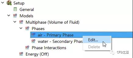
设置主相为air

相同方式设置第二相为water

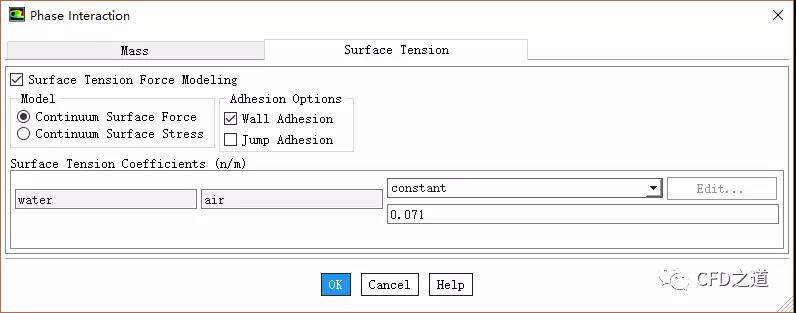
鼠标双击模型树节点Models > Multiphase > Phase > Phase Interactions,弹出对话框中设置表面张力系数为0.071,如下图所示设置
4.5 解释UDF
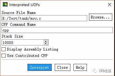
右键选择模型树节点Parameters & CUstomization > User Defined Functions,点击弹出菜单项Interpreted...

弹出对话框中添加源文件mov.c进行解释
4.6 Cell Zone Conditions设置
鼠标双击模型树节点Cell Zone Conditions,右侧面板中设置区域类型为fluid,点击按钮Edit...

激活选项Mesh Motion,设置Zone Motion Function为zonemotion,点击OK按钮关闭对话框

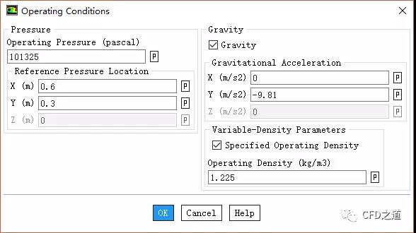
点击按钮Operating Conditions,如下图所示进行设置
4.7 Methods设置
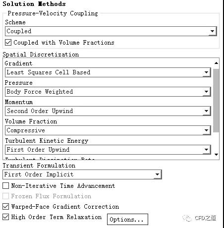
鼠标双击模型树节点Solution > Methods,右侧面板按下图所示进行设置
4.8 Region定义
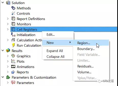
右键选择模型树节点Solution > Cell Registers,点击弹出菜单项New → Region...
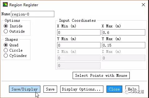
弹出对话框中设置区域(0 ,0)→(0.6,0.15),点击按钮Save/Display
4.9 Initialization设置
鼠标双击模型树节点Initialization,右侧面板点击按钮Initialize
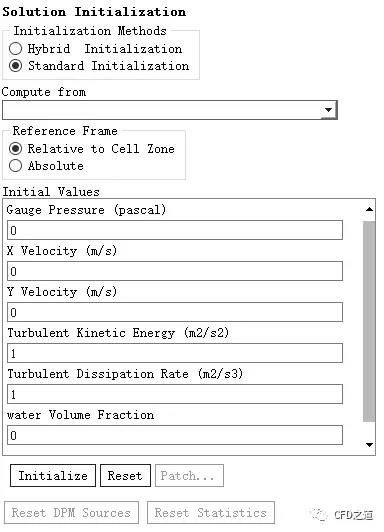
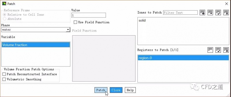
点击Patch...按钮打开对话框,如下图所示,patch前面标记的区域water相体积分数为1
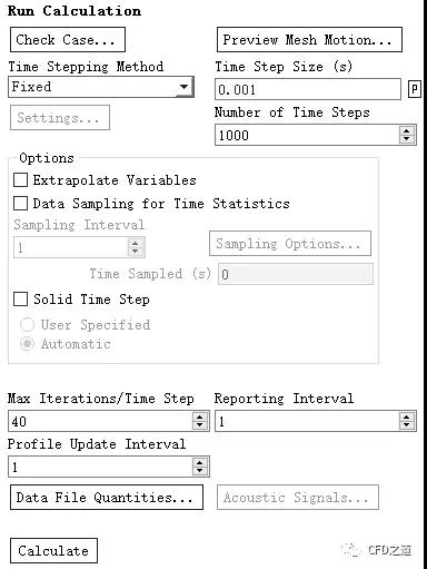
4.10 Run Calculation
双击模型树节点Run Calculation,右侧面板设置Time Step Size为0.001 s,设置Number of Time Steps为1000
设置Max Iterations/ Time Step为40
点击按钮Calculate开始计算
5计算结果
计算完毕后1s时刻液面形状如图所示。
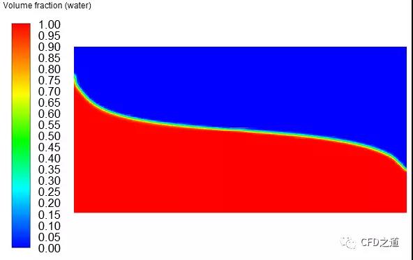
注:经常有人问如何输出液位高度变化。其实很简单,做一个iso surface,定义water的volume fraction为0.5,然后输出iso surface的坐标就行了。
1案例描述
汽车在颠簸的道路上行驶时,在变加速度作用下,可能会导致油箱内液面晃动。当晃动极为剧烈时,甚至会造成油泵无法吸取燃油,因此需要利用CFD研究油箱在晃动过程中液面分布情况。为简化计算,本案例采用2D模型,3D模型的仿真思路及设置过程与此完全相同。计算域几何如图所示。
对于油箱晃动过程,在Fluent中有两种方式进行解决:
指定加速度。Fluent中可以指定流体运动加速度,并将加速度以体积力的形式施加到计算域中的流体上。然而Fluent并没有提供变加速度的直接添加,若要计算变加速度情况,则需要手工分段计算。
指定计算域速度。将加速度或位移数据转化为速度添加到计算域上。可以通过DEFINE_ZONE_MOTION宏或PROFILE文件的方式进行指定。此方式要比加速度方式更加灵活。
本案例假设计算区域的运动速度为:
2模型及网格
案例模型极为简单,在SCDM中创建0.6x0.3m的矩形平面,采用网格尺寸0.003m,在ICEM CFD中生成网格,共生成20000个四边形网格。
3准备UDF
利用UDF宏DEFINE_ZONE_MOTION指定区域运动。
该UDF宏可以以编译或解释的方式加载。
4Fluent设置
以2D、Double Precision方式启动Fluent,导入网格文件
4.1 General设置
双击模型树节点General,右侧面板激活选项Transient及Gravity,设置重力加速度为Y方向-9.81 m/s2
4.2 Models设置
鼠标双击模型树节点Models > Multiphase,弹出的对话框中激活选项Volume of Fluid
激活选项Implicit Body Force,其他参数设置如下图所示
右键选择模型树节点Models > Viscous,点击弹出菜单项Model → Realizable k-epsilon激活湍流模型
4.3 Materials设置
添加材料water-liquid,采用默认材料参数。这里可以将材料参数改成汽油的参数,我就懒得改了,后面就用水代替油了。
4.4 Phase设置
右键选择模型树节点Models > Multiphase > Phase > Primary Phase,点击Edit....
设置主相为air
相同方式设置第二相为water
鼠标双击模型树节点Models > Multiphase > Phase > Phase Interactions,弹出对话框中设置表面张力系数为0.071,如下图所示设置
4.5 解释UDF
右键选择模型树节点Parameters & CUstomization > User Defined Functions,点击弹出菜单项Interpreted...
弹出对话框中添加源文件mov.c进行解释
4.6 Cell Zone Conditions设置
鼠标双击模型树节点Cell Zone Conditions,右侧面板中设置区域类型为fluid,点击按钮Edit...
激活选项Mesh Motion,设置Zone Motion Function为zonemotion,点击OK按钮关闭对话框
点击按钮Operating Conditions,如下图所示进行设置
4.7 Methods设置
鼠标双击模型树节点Solution > Methods,右侧面板按下图所示进行设置
4.8 Region定义
右键选择模型树节点Solution > Cell Registers,点击弹出菜单项New → Region...
弹出对话框中设置区域(0 ,0)→(0.6,0.15),点击按钮Save/Display
4.9 Initialization设置
鼠标双击模型树节点Initialization,右侧面板点击按钮Initialize
点击Patch...按钮打开对话框,如下图所示,patch前面标记的区域water相体积分数为1
4.10 Run Calculation
双击模型树节点Run Calculation,右侧面板设置Time Step Size为0.001 s,设置Number of Time Steps为1000
设置Max Iterations/ Time Step为40
点击按钮Calculate开始计算
5计算结果
计算完毕后1s时刻液面形状如图所示。
注:经常有人问如何输出液位高度变化。其实很简单,做一个iso surface,定义water的volume fraction为0.5,然后输出iso surface的坐标就行了。


最新资讯
-
大卓智能端到端直播实测,16公里复杂路段挑
2025-04-25 17:16
-
《汽车轮胎耐撞击性能试验方法-车辆法》等
2025-04-25 11:45
-
“真实”而精确的能量流测试:电动汽车能效
2025-04-25 11:44
-
GRAS助力中国高校科研升级
2025-04-25 10:25
-
梅赛德斯-AMG使用VI-CarRealTime开发其控制
2025-04-25 10:21
